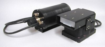
ABIS II soundhead
and electronics bottle. The two housings can be separated by up to 6 feet
(cable length). The large bulkhead connector at center of bottle endcap
connects to the fiber optic cable.
Acoustic, Barnacle Imaging Sonar (ABIS)
For more information, contact Ed Belcher at (425) 488-1331
The Acoustic, Barnacle Imaging System II (ABIS II) mounts on the front of a hull crawling submersible. It is a forward-looking sonar that detects and images fouling, paint condition, and damage on hull surfaces. It is part of a larger program directed by the Naval Surface Warfare Center (NSWC) to autonomously clean hulls of naval ships. The system is called ABIS II because it has a predecessor ABIS I that used four mechanically scanned elements to ensonify the field-of-view. ABIS II images over a 32° field-of-view with 0.25° resolution in cross-range and 3-mm resolution in down-range. It has range settings to view objects from 2.6 ft to 15 ft from the sonar. We expect that ABIS may have other applications as well.
| Operating Frequency: | 3 MHz |
| Number of Beams: | 128 |
| Beamwidth (one-way): | 0.27° horizontal by 8.5° vertical |
| Cross-range Resolution: | 0.37 in. at 7-ft range |
| Down-range Resolution: | 0.125 in. |
| Source Level: | 208 dB re 1 µPa at 1 m |
| Field-of-view: | 32° |
| Dimensions: | Soundhead: | 11.5-in. long by 7-in. wide by 7-in. high |
| Electronics Bottle: | 6.75-in. diameter by 12-in. long | |
| Weight in Air: | Soundhead: | 13.25 lb (negative in freshwater) |
| Electronics Bottle: | 13.5 lb (neutral in freshwater) | |
| Power: (underwater components) |
120 VAC, 20 Watts | |
| Communication link: | 500 ft of fiber optic cable with copper conductors for power | |
| Cable diameter: | 0.5 in. | |
| Communication protocol: | 10 Base T Ethernet | |
|
Display Options
and Frame Rate
|
||
|
Start Range
(ft) |
Image Length
(ft) |
Maximum
Frames/s |
|
2.62
|
2.5
|
9
|
|
5.0
|
7
|
|
|
5.03
|
2.5
|
7
|
|
5.0
|
5
|
|
|
6.29
|
2/5
|
6
|
|
5.0
|
5
|
|
|
7.55
|
2.5
|
6
|
|
5.0
|
5
|
|
|
8.80
|
2.5
|
5
|
|
5.0
|
4
|
|
|
10.06
|
2.5
|
4
|
|
5.0
|
4
|
|
|
|
|
ABIS II soundhead
and electronics bottle. The two housings can be separated by up to 6 feet
(cable length). The large bulkhead connector at center of bottle endcap
connects to the fiber optic cable.
|
 |
|
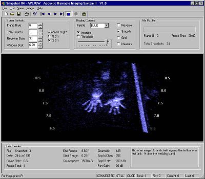
ABIS II display
of two hands in our test tank. Note reflection from wedding ring. The
broad line to the right of the hands is the side of the test tank. Ranges
are in feet from the sonar soundhead.
|
 |
|
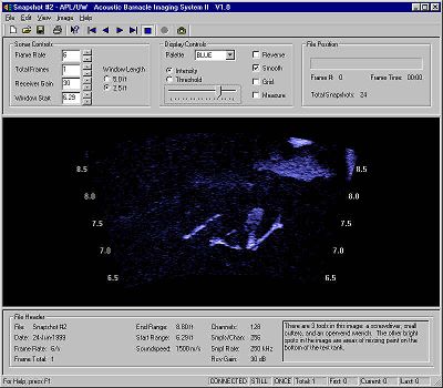
This image shows
three tools 7.25 ft from the sonar. The tool on the left is a screw driver,
the center tool is a pair of cutters, and the tool on the right is an
endwrench partially covering an unpainted patch on the tank bottom.
|
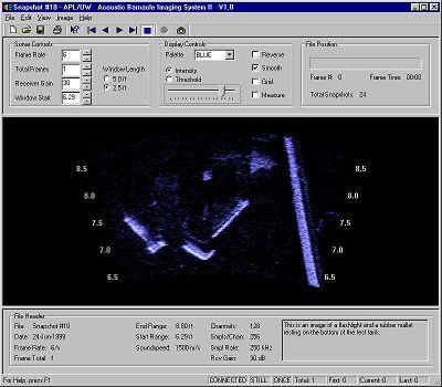 |
| This image shows a waterproof flashlight and a mallet 7.25 ft from the sonar. |
For more information, contact Ed Belcher at (206) 685-2149 or ed@apl.washington.edu
Applied Physics Laboratory
University of Washington
1013 NE 40th Street
Seattle, WA 98105